
Every programming course traditionally starts with a "Hello World" program. These simple programs, displaying only a single line of text, help confirm that the programming environment is correctly set up. This assurance allows programmers to tackle more complex tasks without worrying about configuration issues. However, for embedded programmers, displaying a single line of text is often not feasible or trivial. Instead, they use a simple LED blinking program. This method verifies that the development environment, hardware, and the connection between them are all functioning correctly.
Embedded programmers handle the first program differently. This program takes the form of LED blinking. Simple LED blinking gives embedded programmers much more than "Hello World" does for other programmers. We know then that we have a working development environment. We know we have working hardware. And, equally important, we know that we have a working connection between our development environment and the hardware. When working with Zephyr, we can use a ready-made example that, when loaded, will blink one of the LEDs. So if we have access to any Zephyr-supported development board, we can create our LED blinking as quickly as other programmers create their "Hello World." And what if we have our own custom board? Nothing is lost! In this article, we will show you how to get LED blinking with a custom board. Along the way, we will create a development environment and add the definition of our own board. Let's get to work!
Setting up the environment
For this article, we will be working on the nRF52 DK. And although Zephyr supports this board and it is easy to get a working example for it, we will show how to add support for your custom board.
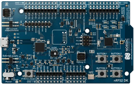
The above set includes, among others:
- SoC nRF52832 (Arm Cortex-M4);
- Segger J-Link OB (on board);
- 4 LEDs;
This is basically everything we need to create our LED blinking.
In one of the previous articles (insert link to the article: https://www.goodbyte.pl/embeddedposts/zephyr-application-development
We described ways to create Zephyr workspaces. For this article, we will use the T2 topology from our repository as the location for west.yaml.
Side note: the entire project described below can be found in the repository https://github.com/goodbyte-software/custom-zephyr-board
First, let's create the directory for our repository and place the manifest in it.
The manifest describes which dependencies we want to use, which version of Zephyr interests us, and which modules.
In the west.yml file (more about the syntax here: West Manifests — Zephyr Project Documentation we encounter the first place where you might need to make modifications. If you are using a microcontroller from a different vendor or with a different architecture, you need to include that in the manifest. Here you will find a list of all available modules: West Projects index — Zephyr Project Documentation Now it's time to download Zephyr and all the necessary modules:
At this point, we have our environment preliminarily configured. We can move on to creating the application and defining our board.
LED Blinking
Let's now add LED blinking to our project. To do this, we will create a simple infinite loop where we will change the state of the LED. Additionally, we need to ensure the project builds correctly. Finally, we will add the description of our board and build the project for it.
main.cpp
In our project, there will be only one source file. There is no need to create more as it is small. See for yourself!
At the beginning of the main function, we check with gpio_is_ready_dt if our pin is ready for use. More precisely, if the port associated with our pin has been properly initialized. Then we move on to line 15 to configure the pin. We set the pin as an output, which should initially be in an active state. What does "active state" mean? It depends. It depends on the hardware we are working with. It depends on what is connected to the output. Finally, it depends on our (or generally accepted) interpretation of phenomena. In the context of an LED, we can talk about the active state as the state in which the LED emits light. We will explain how Zephyr knows which state is active later when discussing the hardware description.
Lines 18-21 are responsible for cyclically changing the state of the LED every second. The gpio_pin_toggle_dt function was used, which changes the pin state to the opposite. You probably noticed that all these functions operate on a structure initialized by the GPIO_DT_SPEC_GET macro. This macro fills the structure based on information stored in the devicetree and assigned to the led1 node. These pieces of information are:
- port,
- pin,
- and additional flags that, among others, describe which state is active.
Let's take a pause here. Just now, a term appeared that I haven't described and may be unfamiliar to some of you. Devicetree, which we are talking about, is a language for describing and configuring hardware. When adding our own board, we will be creating devicetree structures, but at this moment, these two sentences of explanation should suffice.
Build system
Having created the source file, it's time to add it to the build system. Let's create a simple CMakeLists.txt file:
It is worth noting that by including the Zephyr package (line 3), a target named app is also created. We add our source file to this target. This means that the target_sources call should be after find_package.
To build the project correctly, we need to meet one more requirement from the Build System. Namely, the repository should contain a configuration file prj.conf. In our case, this file will remain empty as we do not plan to inject any configuration.
For those using development boards, this is a checkpoint to ensure everything has been done correctly so far. You can check this by building the project for your board. First, however, make sure with the west boards command that west knows your board. If it does, build the project with the following command:
In our case, the board we are using is known to west as nrf52dk_nrf52832. You might be interested in the --pristine flag. If you work with west, you will probably see it many times. This flag tells west not to use any previously generated artifacts from the same project. Rather, it should create them anew. For various reasons, this is the default way of working with west, especially when working on elements that are input when generating source code. Over time, you will discover what these elements are and how many of them there are.
Defining a new board
When adding a new board to the Zephyr ecosystem, we need to remember four mandatory files. These are files for the hardware description layer (Devicetree) and the project configuration layer (Kconfig). We will start with the Devicetree, which consists of one file.
Devicetree is used to describe hardware - also in the Linux kernel. In our case, we need to describe our board, including defining which MCU we use and how our LED is connected. In our example, we use nRF52 DK, which is crucial for this step. First, we need to create a directory for our board description:
The boards directory should have the structure: boards/<architecture>/<board_name>. In our case, the microcontroller is nrf52832, which contains an Arm Cortex-M4F. We named the board goodbyte-demo.
Now, let's create the file led-blinking/app/boards/arm/goodbyte_demo/goodbyte_demo.dts. It looks like this:
That's a lot of information at once, right? Let's break down this file and explain the purpose of each line. The file starts by specifying the syntax version (/dts-v1/;). Next, it includes the file describing our microcontroller, which is nordic/nrf52832_qfaa.dtsi. Note that in the devicetree, files with the extension .dtsi contain definitions of available hardware. By default, everything defined in .dtsi files is disabled, so you need to enable the specific node to use it. You can find the description of your microcontroller in the led-blinking/zephyr/dts directory, which was downloaded when you first ran the west update command.
The main node definition starts in line 6. The model property describes the board, while the compatible key determines what the node actually represents. We won't go into the details of bindings here, but interested readers can refer to: Devicetree bindings — Zephyr Project Documentation.
Next, we need to select the RAM and FLASH to use, configured by the values entered in the zephyr,sram and zephyr,flash keys. To determine what should be entered, refer to the description of your microcontroller. In the nordic/nrf52832_qfaa.dtsi file, we find the following nodes:
For other MCUs, these devices might have different names. Therefore, you need to verify this. Meanwhile, let's move on to defining the LEDs we will use. Let's take another look at our LEDs:
At this point, it's important to note that led_1 is the name of a new node. The full path of this node is /leds/led_1. Meanwhile, led1_label is the label of our node, which we can reference in C/C++ code or within the devicetree.
As you can see, each LED is “compatible” with the general gpio-leds device. This means it can contain properties like gpios and label. Only the gpios property is required and contains information about the pin associated with the LED. The line gpios = <&gpio0 17 GPIO_ACTIVE_LOW>; directly results from the connection of the LED on our development board.
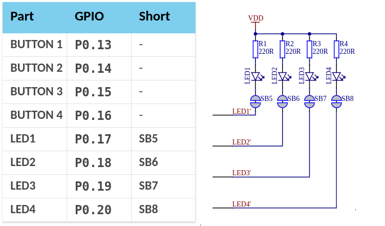
From the above image, we can see how we defined our led1:
gpio0- port 0,17- pin 17,GPIO_ACTIVE_LOW- the LED emits light when the pin is low (active state).
As you may remember from our example in the main.cpp file, we referred to our LED using the DT_ALIAS(led1) macro. This follows the Blinky example from Zephyr. To ensure our program compiles correctly, we need to define this alias. The following lines from goodbyte_demo.dts serve this purpose:
Note the use of the node label when creating the alias. You cannot use the name led_1 here because you cannot refer to the node's name or its full path.
In addition to the main node /, we enable the peripherals defined for our microcontroller, which are gpio0 and gpiote. How did we know which nodes to enable? We know our LED uses gpio0, and in the file zephyr/dts/arm/nordic/nrf52832.dtsi, which is indirectly included in our .dts file, this node is defined as follows:
Therefore, we had to change the status of this node from disabled to okay to properly initialize the peripheral. The same was done for the gpiote node associated with gpio0.
That's all for the devicetree. Now, let's move on to the next layer I mentioned earlier. To finish adding a new board to our project, we need to create Kconfig configuration files. In Zephyr, Kconfig is used to configure functionalities. To ensure our application builds correctly, we need to create three Kconfig files:
- Kconfig.board - Required to make our board available in the project configuration. In our minimal example, it looks like this:
- Kconfig.defconfig - This file configures default values when someone uses our board. The file is usually enclosed with
if BOARD_NAME/endif.
- goodbyte_demo_defconfig - This file contains the default configuration for our board. The options selected here can be overridden in the project configuration file (
prj.conf). Typically, configurations that are always true for our board, such as microcontroller settings and used peripherals, are placed here.
With our board configured this way, we can build our project. To do this, first add the following line to app/CMakeLists.txt just before the line containing find_package(Zephyr):
This ensures that when west searches for known boards, it will also look in our newly created directory. Now, let's build our LED blinking project!
Voilà! The project is compiled! Notice one thing - previously, we built the same source code for a different board than we are using now. The source code itself hasn't changed at all. That's what we call portability! If you're eager to flash it to your board, head to the next section.
If you encounter any issues during the configuration and the compilation doesn't even start, here are a few paths to check:
build/zephyr/zephyr.dts- the complete description of our hardware, considering everything we've used and overridden from the original .dtsi file.build/zephyr/include/generated/devicetree_generated.h- a header file generated from thezephyr.dtsfile, indirectly included in ourmain.cppthroughzephyr/drivers/gpio.h.build/zephyr/.config- all available Kconfig options, whether they are set, and their values.
Debugging and Flashing
Unfortunately, it won't be that simple. We're not saying it will be difficult either. However, to be able to program the board, we still need one thing: the configuration of debugging tools. We use nrfjprog and JLink, which are included on the development board. Therefore, we need to add the configuration for our board to CMake. Below, you can find our configuration:
Only after having this file can we flash our firmware to the board:
Summary
Embedded programmers often start their journey with new solutions using an LED blinking program. In this article, we showed how to do this with Zephyr, both with a supported board and with hardware entirely designed and built by us. A significant part of this article is dedicated to adding a new board definition. Initially, working with Zephyr involves more time in the configuration phase than in the programming phase. However, this investment pays off. This way, transitioning to a new version of hardware becomes much simpler.


